Description
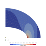
Find the displacement in x- direction of point A of hemisphere shown in Figure 1.
Reference
- NAFEMS Finite Element Methods & Standards, The Standard NAFEMS Benchmarks, Test No. LE3. Glasgow: NAFEMS, Rev. 3, 1990.
Analysis type
Linear Static Analysis
Technologies used
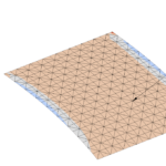
- Meshing: Gmsh, NetGen
- Solver: Calculix
Geometry

Load assumptions
Concentrated radial loads of 2 kN outward at A, inward at C.
Boundary conditions
- Point E, zero zdisplacement
- Edge AE, symmetry about zx plane, i.e. zero y displacement, zero normal rotation
- Edge CE, symmetry about yz plane, i.e. zero x displacement, zero normal rotation
- All other displacements on edge AC are free.
Material properties
Isotropic, E = 68.25 GPa, ν = 0.3
Computation target
Displacement in x- direction of point A = 185 mm
Results


Summary
| Theory | Gmsh+CalculiX | Error |
| 185 mm | 185.66 mm | 0.36 % |
| Theory | NetGen+CalculiX | Error |
| 185 mm | 184.51 mm | -0.27 % |
Conclusion
CalculiX results are comparable with theoretical results.