Industry: Agricultural Equipment
Challenge: To ensure effective cooling of the Syntrac 400’s engine bay at both stationary (0 km/h) and operational (10 km/h) conditions, a comprehensive heat balance and airflow simulation study was conducted using computational fluid dynamics (CFD).

Objectives:
- Analyze airflow patterns: Identify the distribution and velocity of cooling air within the engine bay.
- Evaluate pressure distribution: Determine the pressure distribution throughout the engine bay, including areas of high pressure and potential airflow restrictions.
- Assess temperature distribution: Map the temperature distribution within the engine bay, identifying areas of high heat concentration and potential cooling inefficiencies.
- Determine pressure resistance: Characterize the relationship between cooling air volume flow rate and pressure drop, representing the system resistance.
- Select preliminary cooling components: Propose suitable fans and fan drives based on the simulated cooling requirements.
Methodology:
- CAD Model Simplification: A simplified CAD model of the Syntrac 400 engine bay was created to optimize computational efficiency while maintaining relevant details.
- Boundary Conditions: Realistic boundary conditions were defined, including ambient temperature, heat sources from the engine and hydraulic components, exhaust system temperature, and cooling air inlet temperature.
- CFD Simulations: CFD simulations were performed for two scenarios:
- Stationary (0 km/h): Representing the engine bay at rest, with no additional airflow due to vehicle movement.
- Operational (10 km/h): Simulating the engine bay under normal operating conditions, considering the impact of vehicle speed on airflow.
Results and Discussion:
Stationary Conditions (0 km/h):
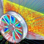
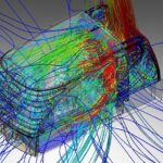
- Airflow Patterns: The simulations revealed that the cooling air entered the engine bay primarily through the front grille and was directed towards the heat sources.
- Pressure Distribution: A high-pressure zone was observed around the engine, while lower pressure regions were present near the exhaust system and under the vehicle.
- Temperature Distribution: The highest temperatures were concentrated around the engine, with a gradual decrease towards the outer edges of the engine bay.
Operational Conditions (10 km/h):
- Airflow Patterns: The additional airflow due to vehicle speed enhanced the overall circulation of cooling air within the engine bay.
- Pressure Distribution: The pressure distribution was generally similar to the stationary case, but with slightly higher pressure levels due to increased airflow.
- Temperature Distribution: The temperature distribution remained largely unchanged compared to the stationary case, indicating that the increased airflow was sufficient to maintain effective cooling.
Pressure Resistance Curve:
The CFD simulations provided the pressure resistance curve, which relates cooling air volume flow rate to pressure drop. This curve is essential for selecting appropriate fans that can deliver the required airflow while overcoming the system resistance.
Preliminary Cooling Component Selection:
Based on the simulated cooling requirements, preliminary fan and fan drive selections were proposed for the charge air and water cooler, as well as the oil cooler. These recommendations serve as a starting point for further design considerations and component optimization.
Conclusion:
The CFD analysis of the Syntrac 400 engine bay cooling provided valuable insights into airflow patterns, pressure distribution, temperature distribution, and pressure resistance characteristics. These findings will guide the design and selection of cooling components to ensure optimal cooling performance under both stationary and operational conditions.
Are you facing challenges in optimizing the thermal performance of your construction equipment?
CFD simulations can be a powerful tool to analyze airflow patterns, pressure distribution, and temperature distribution within your designs. This allows for proactive optimization of cooling systems, ensuring efficient operation and extended equipment lifespan.
Contact us today to discuss how our CFD expertise can help you achieve optimal thermal management in your next project.